So for now we can add the rooms/spaces, doors, windows/glazing, and shades and as of recently, plenums.
But what about openings for continuous spaces/rooms like long corridors broken into smaller ones, or large open workstations that have a perimeter zone.
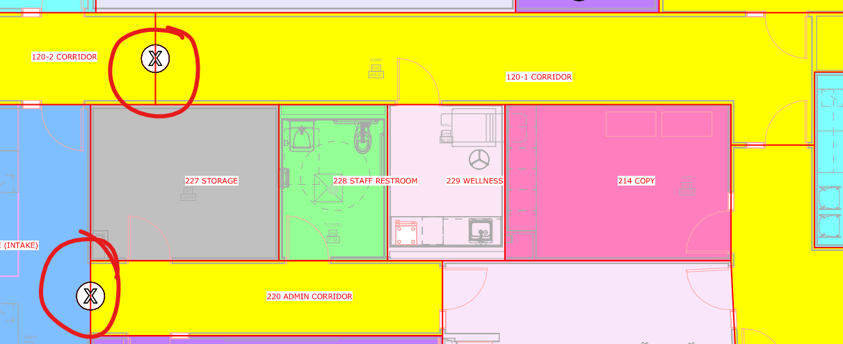
Something i do in my workflow is place a generic model family that serves as my “opening tracker”
I will then import the backgrounds and i can quickly see which rooms need to have openings/holes.
Spitballing here, what if there was a way to detect a specific family intersection (something the user manually places) across a room/space boundary/separation line that would then serve as an indicator that tells the room/space wall to have an opening?
I need some help to make sure I understand your wish here correctly. I see two steps in the process here:
A visual indicator to quickly find the edges that should be set to openings (or as we call it in Pollination/EnergyPlus world, Air Boundaries.
A solution to set the walls to AirBoundaries so they get exported to IESVE as holes.
For the first one, we don’t have an official solution, but if you put generic model families in your Revit model, then you can export them as shades and import them to Pollination. Suppose you can put a simple, generic model that generates simple shade geometry. You can export those as shades, and once you have them in the model, we can technically automate the step for running the intersections and changing the walls to air boundaries in the Model Editor using a Python script.
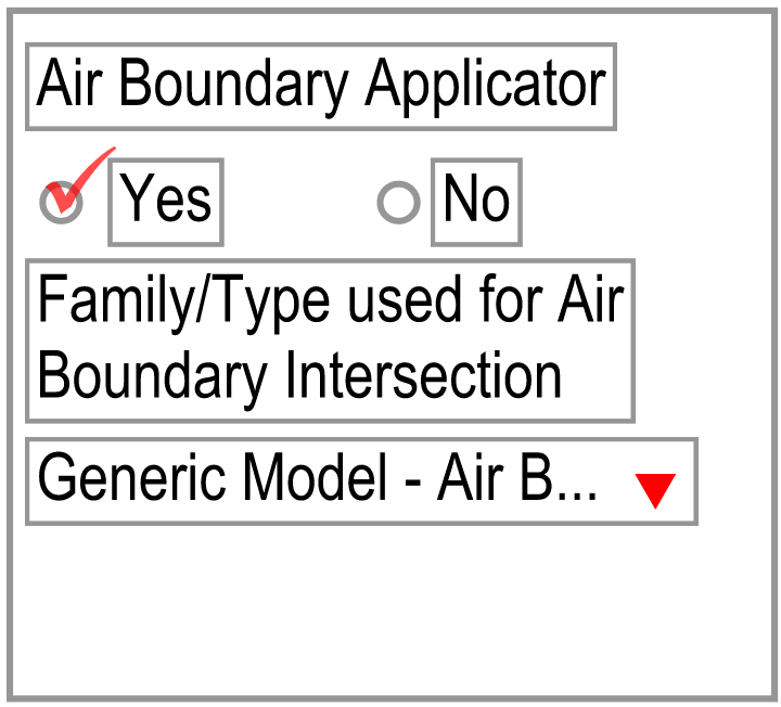
For the second one, we already have a command. As you can see in the command documentation, the command can use lines as a guide to set those faces.
Ah yes, I am referring to Air Boundaries. And you understood correctly. The “generic model element” would be the indicator that sets the walls as air openings ideally as the user runs through the Pollination app.
The reason for this idea was simply due to the fact that we are already doing a lot of the room/space related work in Revit (space type, naming, occupancy tracking, equipment, etc., etc.) to get it ready for Pollination. As we are panning around in the model it’s easy to place this “generic model element” to tell us to make this an air boundary (internally or externally of Pollination).
I figured this air boundary step could be one that could get simplified by using this “element intersection” across the room/space boundary line rather than having to jump back and forth between the model editor and the Revit model to track the air boundaries that need to be applied.
So instead of converting this element to a shade and running script in the model editor like you said this could be a setting along the Pollination steps prior to exporting???
The idea again being that the user does all their work in Revit without having to jump back and forth between Pollination and Revit to track down their Air Boundaries and/or having to run a separate script.
Now, I have not tried using a script to automate this which could just as simple. So, I will give this a shot and see how testing goes. Again, just spit balling an idea.
The sample Revit model with the generic families would work. I thought you might already have it exported as a snapshot, which will make it easier to share.
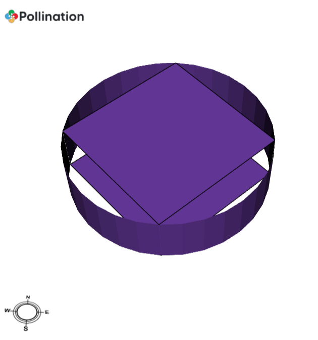
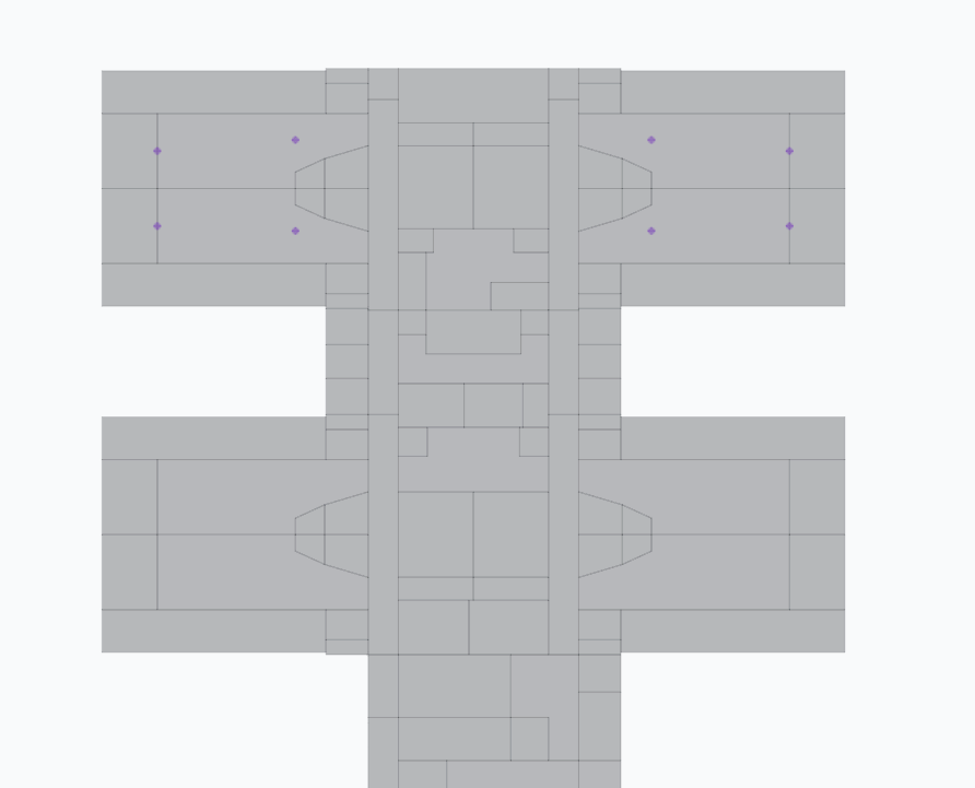
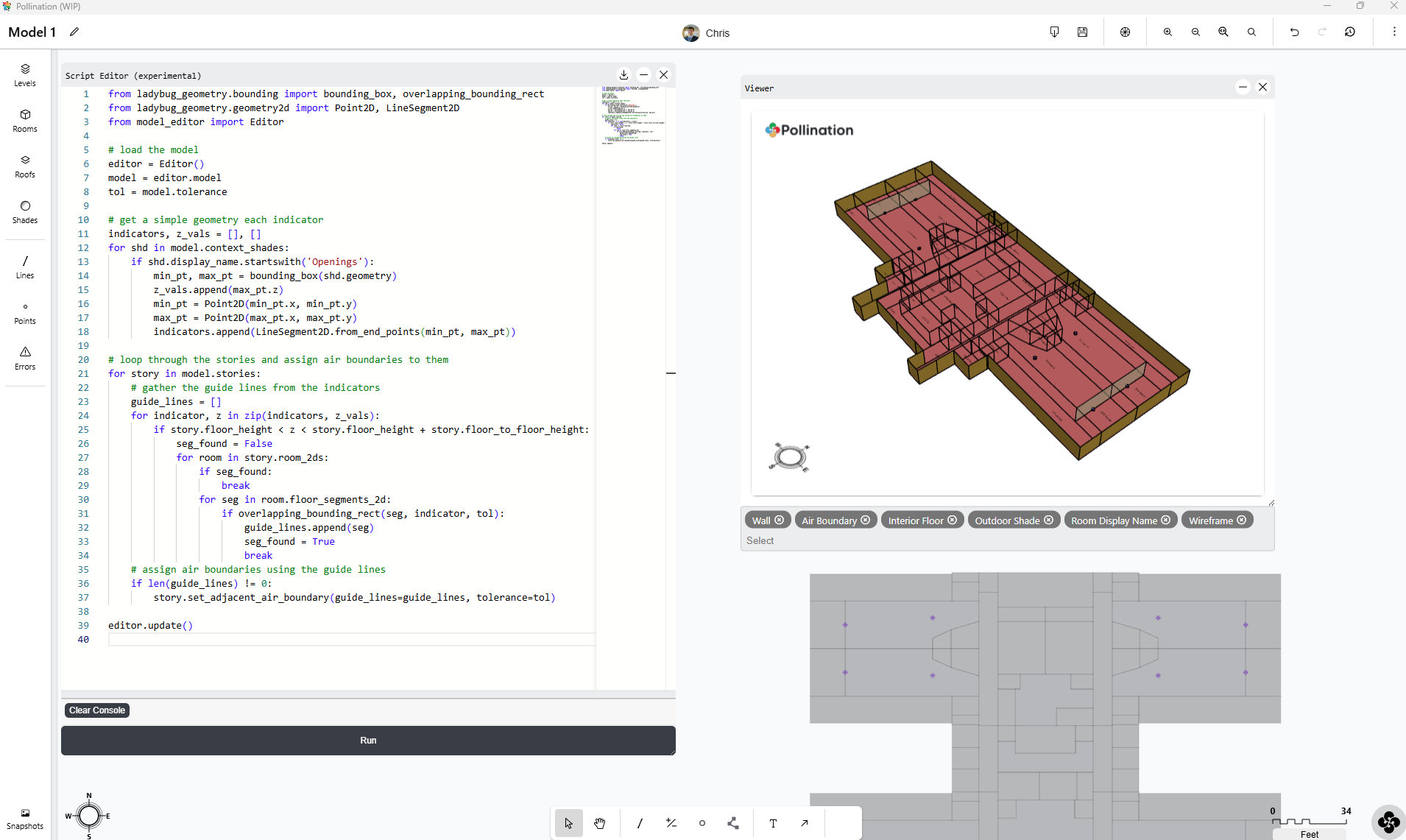
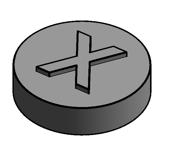
I’m fairly confident that I can write a script to do what you are asking but I’m having a little difficulty understanding your files. Am I right that this sample you gave us in SPACES.pomf is showing 8 of these opening indicator objects (I guess they are the circle-looking shades).
I went ahead assuming that everything I said above is correct. Here is your script:
from ladybug_geometry.bounding import bounding_box, \
    overlapping_bounding_rect
from ladybug_geometry.geometry2d import Point2D, LineSegment2D
from model_editor import Editor

# load the model
editor = Editor()
model = editor.model
tol = model.tolerance

# get a simple geometry for each indicator
indicators, z_vals = [], []
for shd in model.context_shades:
    if shd.display_name.startswith('Openings'):
        min_pt, max_pt = bounding_box(shd.geometry)
        z_vals.append(max_pt.z)
        min_pt = Point2D(min_pt.x, min_pt.y)
        max_pt = Point2D(max_pt.x, max_pt.y)
        indicators.append(LineSegment2D.from_end_points(min_pt, max_pt))

# loop through the stories and assign air boundaries to them
for story in model.stories:
    # gather the guide lines from the indicators
    guide_lines = []
    for indicator, z in zip(indicators, z_vals):
        ceiling_height = story.floor_height + story.floor_to_floor_height
        if story.floor_height < z < ceiling_height:
            seg_found = False
            for room in story.room_2ds:
                if seg_found:
                    break
                for seg in room.floor_segments_2d:
                    if overlapping_bounding_rect(seg, indicator, tol):
                        guide_lines.append(seg)
                        seg_found = True
                        break
    # assign air boundaries using the guide lines
    if len(guide_lines) != 0:
        story.set_adjacent_air_boundary(
            guide_lines=guide_lines, tolerance=tol)

editor.update()
The script should work well for your particular indicator on multi-story models and those with other types of context shade elements. The only requirement that you’ll need to do to get it to work is that you must use the Solve Adjacency command on the model before running the script.
Hope that helps and just let me know if I misunderstood anything.
I marked this discussion as done now that you have the script, but let us know if you need anything else.
Also, as you might have noticed from the code, it will work with any shade objects as long as the name starts with Openings. I’m saying that in case you may want to simplify the shape of the generic model to a simpler box in Revit.