Windows/Glazing - Merging and Offsetting

Thank you for joining me on this journey as I make my way through my first pollination model :grinning: We are almost there!

Question 1: Merging and Offsetting Windows
I am trying to edit the windows on my building to merge them into a few mega-windows. Then I also want to make sure that they are offset from the ceiling, ground, and room edges. I saw you do this at IBPSA, but is this feature public yet?

Question 2: Exporting from Snapshot Manager
I am trying to export into IDF or OSM (ideally OSM, but will take either) from the Snapshot Manager (WIP). OSM doesn’t appear as an option, so I am going with IDF for now. I press Download and it shows as successful in the bottom right corner, but the saved IDF file is nowhere to be found. Is there a way to see the saved file path?

1 Like

Hi @eschwartz,

It has been awesome to see the journey! We are looking forward to hearing your feedback and feature requests like this one. :raised_hands:

Question 1: Merging and Offsetting Windows

We haven’t exposed the Simplify Windows in the model editor yet. We should be able to include it in the public release soon. cc: @antonellodinunzio

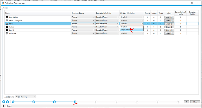
You can select the option when you export the model from Revit but I imagine it is too late to do that at this point! :smiley: See step 4.

If you save your model as an HBJSON and send it to me in a private message, I can simplify the windows for you in Rhino and send back the model. Let me know if that helps.

This is already implemented and is called Rebuild Apertures.

image

Question 2: Exporting from Snapshot Manager

That is expected. We will add the export to OSM soon, and I will make sure to send you a note once it is available.

Oops. I never had this issue! There is always a pop-up that shows where the file is. In my case, it goes to the default download folder. Does it only happen for export to IDF or does it happen if you try to export another format? Say HBJSON?

@antonellodinunzio what is our approach for selecting the target folder?

Question 1 response:
Excited for merging/ mega window down the line!

If you are taking feature requests, doing the “Rebuild Aperture” button with an adjustable offset from the edge, would be amazing. We model our glazing with frames that take up 4-6 inches.

Question 2 Response:
Excited for OSM export in the future!

No file type shows where it exported to. HBJSON and IDF give me a “successful export”, and GEM, INP, and RAD fail (not that I need them, just checking all the boxes). I am wondering if the little gray box next to the “Download” button on the export drop down is supposed to do something? If so, it is not at the moment. I have checked the downloads folder, documents folder, C:\Users\eschwartz\AppData\Roaming\pollination\snapshots folder… anywhere else I should be looking?

export window
successful export

Taking feature requests and making them happen is all we do! :slight_smile: Let me make sure that I understand this correctly. This might deserve its own separate command.

Are you looking for a command that offsets all the windows by a certain distance? Or do you want this command to be implemented to the windows only if they are touching the edge of the room or the edge of another aperture?

That is a stop button for canceling a command while it is running. Doesn’t do anything interesting for this command.

Hmm. Can you check the downloads folder on your machine? Can you see the files there?

Downloads folder is empty of any idf files. I can save it as the DFJSON file, but nothing else. I can export to idf or osm from the “Export Model” manager, but that obviously doesn’t have all of the alignment edits that I did in the Snapshot Manager- in your own words, the walls are still drawn like an artist!

1 Like

Thank you for testing! “The artistic approach” always gets me! :smile: I sent you a private message. It looks like this is a case that we should debug together over a call and report back here.


I do best with pictures- here is a screenshot of sketchup with 3 windows and I marked 1’ offset from all room sides, ceiling, and floor with the tape measure tool/ dashed line. Window 1 is clearly within the offsets and wouldn’t need to change at all. Window 2 is touching the side and bottom offset lines, but is fine on top. Window 3 is touching all 4 offset lines. All 3 maintain an offset, but if they were to cross the dashed lines, there would be an error. 1-ft offset is a very conservative and doesn’t need to be that much, but over 6" is our rule of thumb.

We are aware that sometimes windows (e.g. storefront or spandrel) go floor to ceiling, but currently we adjust the width to compensate and maintain the same area and window-to-wall ratio.

1 Like

The issue with exporting from Snapshot Manager was a bug that is fixed now.

The merging and offsetting of the windows is a feature request that we need to work on. @chriswmackey, I will document the feature request for you on Basecamp. It feels like it can be an additional input for the Rebuild Apertures command to adjust the border for adding frames to them.

Thanks, @eschwartz and @mostapha ,

This is very doable:

In fact, you can probably get this all to happen right now in the model editor by changing the model tolerance to whatever frame offset distance you want to use and then running the “Rebuild Windows” command. But we should add a more formal way of doing this because playing with the model tolerance can be a little like playing with fire if you’re not careful.

FYI, @eschwartz , right now you should find that your model tolerance is around 3 mm, which means that running the “Rebuild Windows” command will offset all of your windows to be 3mm from the edge of the parent Face. This will get the windows to display nice in Sketchup and the OpenStudio App and EnergyPlus will not complain about it. The nice thing about only offsetting to a tolerance of 3mm is that it won’t change your glazing ratio significantly, which can be important for things like the storefront case you mentioned. But am I correct that your goals here with the frame are different and you would rather have the glazing reduced a little in order to have a larger frame?

If you can confirm that my understanding above is correct, I can just add a “parent offset distance” variable into the “Rebuild Windows” command. This will allow you to offset the windows from the parent edges to be something other than the model tolerance.

You are right that we have somewhat 2 problems here- 1) more of an offset than 3mm to accommodate frame width and 2) reducing size of windows.

In my opinion, the first problem is more of an issue since the model will not run if you add frames and they hit/overlap the room edges. Naturally, frames are important for capturing thermal transfer through windows and we always want to include them in our energy models.

The second problem is also important because a reduced window-to-wall ratio will under estimate energy usage. The critical question is by how much, but that is too big of a question to answer since it depends on window size (and its reduction), window type, and building type.

My priority is moving the windows away from edges, even if it means shrinking the windows, but in some ideal world, the script would go something like:
User input: how much do you want the window to be offset from edge (ceiling, ground, both sides) by: x inches (over 6 inches if software cant take user input)

Program:
Check 1: move full window down x inches (without changing area)
Check 2: move full window right x inches
Check 3: is window x inches from bottom
if Yes- green light
if No- outline in red
Check 4: is window x inches from left
if Yes- green light
if No- outline in red
Check 5: is window x inches from adjacent window(s)
if Yes- green light
if No- outline in red
Message: We found y windows that worked and z that didn’t.

User: look at the z windows that didn’t and choose to either ignore, merge, or resize. Program would need to be able to override the red outline, merge with another window, or resize a window.

Ahhh, I think I understand now. I think I have just never gotten this deep into the weeds with using EnergyPlus’s WindowProperty:FrameAndDivider object.

Am I correct that this WindowProperty:FrameAndDivider is what you are referring to when you say “frames” and, when you say “the model will not run”, you are taking to the following Fatal error that EnergyPlus throws if your glass + frame area exceeds the area of the parent Face?

   ** Severe  ** ProcessSurfaceVertices: Base Surface="FACE_69159444", 
   **   ~~~   ** Window Surface="FACE_69159444_GLZ0" area (with frame) is too large to fit on the surface.
   **   ~~~   ** Base surface area (-windows and doors)=[0.15] m2, frame area=[1.63] m2.
   ** Severe  ** ProcessSurfaceVertices: Base Surface="FACE_E634D5D4", 
   **   ~~~   ** Window Surface="FACE_E634D5D4_GLZ0" area (with frame) is too large to fit on the surface.
   **   ~~~   ** Base surface area (-windows and doors)=[0.15] m2, frame area=[1.63] m2.
   **   ~~~   ** For explicit details on each unused construction, use Output:Diagnostics,DisplayExtraWarnings;
   **  Fatal  ** Errors found in Building Input, Program Stopped
   ...Summary of Errors that led to program termination:
   ..... Reference severe error count=2
   ..... Last severe error=ProcessSurfaceVertices: Base Surface="FACE_E634D5D4", 
   ************* Warning:  Node connection errors not checked - most system input has not been read (see previous warning).
   ************* Fatal error -- final processing.  Program exited before simulations began.  See previous error messages.

If so, I’m glad to meet someone using this object in professional practice. I exposed the WindowProperty:FrameAndDivider object in our Pollination schema ~2 years ago but I wasn’t sure if I and a few other researchers/hardcore IDFEditor people were the only ones making use if it. More often than not, I get people asking how they can just simplify the window geometry to something that doesn’t account for frames at all and then people just want to account for frames in the U-values and SHGC they assign with a WindowMaterial:SimpleGlazingSystem object. But I’m all for making use of the FrameAndDivider object. It’s clearly a much more robust way of modeling the windows, though you really need to model the window geometry right in order to make use of its improved accuracy.

I guess I always expected people using this FrameAndDivider object to model the window glass geometry exactly as it is on the real building, which would mean that this would not really be a concern:

The researchers I know doing this right now use the Rhino plugin for this since it gives you the freedom to edit the window geometry to be anything you want. We can certainly implement some Model Editor routines that get you close to this freedom but you’re looking at a steeper learning curve in order to be able to get more freedom to change the window geometry. At a certain point, it may just be easier to learn a little Rhino.

In any event, let me start by just adding a “parent offset distance” variable into the Model Editor “Rebuild Windows” command so this never blocks you from making a simulate-able model with the FrameAndDivider object. I feel like the program you proposed might be changing the window geometry a little too much from the original window glass geometry that you’ll lose much of the improved accuracy that the FrameAndDivider object offers over the WindowMaterial:SimpleGlazingSystem approach. For one, the area of center-of-glass to edge-of-glass could get messed up. I’m not against adding something like it but let’s just make sure that none of the other options we have implemented would work for you first before we do something so custom.

Yes, I am referring to WindowProperty:FrameAndDivider object. And yes, when I say “will not run”, I mean it will throw a fatal error.

I know many people that use simple glazing and compensate for assembly U-factors and SHGC. We have found that simple glazing has its downfalls, particularly in accurately modeling SHGC. Given that glazing has the ability to dramatically impact both heating and cooling, we try to be as robust as we can.

We already somewhat mess up the center-of-glass to edge-of-glass ratio when we merge windows (aka making mega windows) and that’s just one of those assumptions we put out there since modeling tons of individual windows increases modeling run time.

I know there is no perfect answer, just trying to be as goldilocks as we can, especially as we are just starting to use pollination! :tada:

2 Likes

Hi @eschwartz ,

We finished adding an option for the “parent edge offset” into the Model Editor “Rebuild Apertures” command:

So you can set this to something like 1 foot and you will see that all of the apertures in the model are offset 1 foot inwards from the parent face.

This should help ensure that you always have a way to avoid the EnergyPlus error if the fenestration area + frame is larger than the parent face area.

Next, we can work on finishing up the “Simplify Apertures” command that Mostapha mentioned earlier in this thread. This will enable you to merge windows together if they are close to each other within a “merge distance” that you can adjust. Altogether, the “Simplify Apertures” merging process will add some extra glass area for the frame space in between the window elements while this “parent edge offset” in the “Rebuild Apertures” command will take some of the glass area away. So hopefully the result that you’ll get between the two commands is pretty close to the original glass area. But we can re-evaluate whether we need something fancier or more custom like the step-by-step program you mentioned once we have gotten the “Simplify Apertures” command integrated.

Hi @eschwartz, both of the features are now fully implemented. See the export options, and the simplify windows command in the latest release. Feel free to open a new topic in case you need a new feature! Thanks again for all the helpful suggestions.