I’m exploring whether Pollination could help automate the extraction of thermal bridge lengths directly from the building geometry - Model Editor. For example, calculating linear intersection distances between:
roof and wall
wall and window/door openings
wall and slab/foundation
wall and balcony or other projections
window-to-slab junctions, etc.
The idea is to streamline compliance with standards and certifications that now require detailed accounting of thermal bridges — not only Passive House (PHI/PHIus) projects, but also NECB and the CaGBC Zero Carbon Building Standard (ZCB), where most thermal bridges must be included in the energy model in some ways.
At the moment, most teams rely on manual take-offs but it seems like Pollination’s geometry engine could be leveraged to automate these measurements.
Has anyone here already developed a workflow or script to do this in Pollination? Would there be interest in building a community-driven approach to automate thermal bridge quantification?
Thanks in advance — looking forward to hearing your thoughts!
PS : I find this guide from BC Hydro really usefull for reference :
Yes. This should be possible. Some of them are easier to calculate and straightforward but some might need a bit more work like the one for the balcony which is hard to identify automatically for floating balconies that are modeled as shades.
We’re in the process of adding an area takeoff report to the Model Editor. Depending on the desired format for the output we might include these values in the same report or create a new report that generates these values.
It will be up to @mikkel to make the call on this.
@edmay has a Passive House extension of honeybee: honeybee-ph which can create a PHPP model or a WUFI model if your not a fan of the German flavor of passive house.
Moreover there are tools for thermal bridges, perhaps that could be of use in this endeavor?
Can you be more specific about the thermal bridging tools that @edmay has developed? We discussed adding new methods to the core library for calculating these values. We can learn from his approach, and try to make our implementation reusable for HB-PH.
I’m also adding @chriswmackey here to keep him in the loop.
Also there is this: GitHub - rd2/tbd: Thermal Bridging & Derating that is a measure that: " An OpenStudio Measure that first autodetects major thermal bridges (like balconies, parapets and corners) in an OpenStudio model (.osm), and then derates outside-facing, opaque surface constructions (walls, roofs and exposed floors). It interacts with the OpenStudio SDK and relies on AutomaticMagic’s Topolys gem, as well as rd2’s OSut gem."
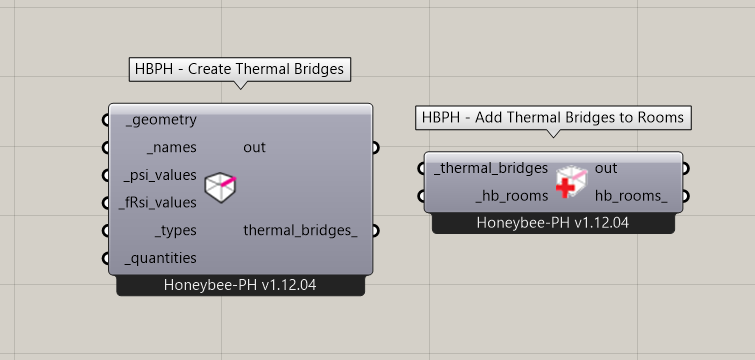
Ed can obvs explain better but he’s got a component to create thermal bridges, inputting all the necessary values etc
I have used the TBD measure with Ladybug Tools-exported models in the past and it works well. It is probably the solution that I would recommend for anyone who needs to account for thermal bridges in an OpenStudio simulation. But I am not sure whether @rbs is using OpenStudio here for modeling thermal bridges.
It would also be good to know what @edmay 's methods are in the honeybee-ph components that he developed (if he sees this) in case there is anything specific about passive house thermal bridges that we should be aware of.
But, whatever the case, it seems generally useful for me to add some core library properties for the following edge geometries taken from Honeybee Rooms:
roof_to_exterior_wall_edges
slab_to_exterior_wall_edges
exterior_aperture_edges
exterior_door_edges
We can use these in a report to make some clear visualizations and just sum the lengths of the edges to give guidance on construction derating for thermal bridges. I’ll plan to add these methods tomorrow.
At Akonovia, we rely on a range of tools depending on the project context and the preferences of each energy modeler. Our toolbox includes OpenStudio, eQuest, IESve, RETScreen Expert, WUFI Passive, METr, and HAP V6.2. As an MEP firm, we also produce our plans in Revit, which is why we recently started integrating Pollination into our workflow. Since we have access to the architectural model very early in the process, it’s a natural fit.
One of our main goals with the Model Editor is to leverage its flexibility to extract geometry information, such as thermal bridge lengths, right from the start. A useful reference on how to classify and account for thermal bridges is the BC Hydro Thermal Bridging Guide, along with their Excel tool for wall U-value depreciation. Essentially, this sheet rationalizes thermal losses from each thermal bridge (linear and point) by converting dimensions into W/°C. This makes it possible to aggregate all losses consistently, since they are expressed in the same unit.
As a CPHC with PHIus, I’m also used to treating thermal bridges in a slightly different way: rather than depreciating the overall wall value to obtain a global transmission coefficient, each thermal bridge remains counted separately. This makes it easier to identify and address the weakest-performing elements directly, which is often more transparent from a design optimization perspective.
For reference, here’s all the TB BC Hydro Account for :
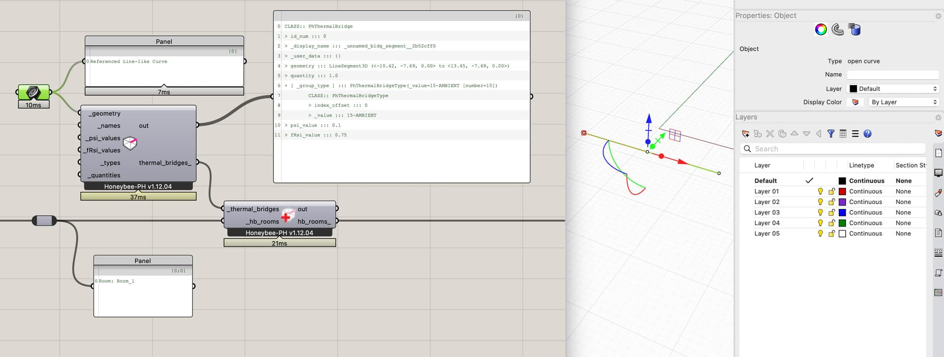
the actual geometry (a Polyline3D representing the length across the facade).
At export, the TB lengths are calculated, and the relevant values structured for either WUFI-Passive or PHPP.
FWIW, this has worked well so far and we use it on all our PH projects.
Note a couple things:
The Psi-Values and fRsi values themselves are calculated outside of Rhino. We use a software named ‘Flixo’ for this.
Currently the curves are all hand-drawn in the Rhino model and usually ‘tagged’ with a name or ID of some form so we can organize it all properly. I agree that it would super neat to be able to automated the generation of these.
Implementation Thoughts:
One small nuance we found when implementing, in case it is helpful food for thought for your work, was that it was ambiguous in practice which HB-Room a TB is ‘in’ since by definition they almost always occur at a boundary between two HB-Rooms. We decided to implement the HBPH-TBs as a ‘singleton’ so that no matter what the user does, they can’t accidentally double-count them.
We have also found that it is super duper important for us to be able to track the ‘source’ of the data, since it comes from outside the model. We use a small HB extension (honeybee-ref) in order to also log all of the reference links to this backup documentation / DB-records where the data comes from.
It’s worth pointing out a subtle but important difference between Passive House and nearly all other frameworks when considering the transitional thermal bridges. The Psi and Chi factors are developed in consideration of defining the assembly areas by either their external dimensions, or internal dimensions. Either is correct, but when you apply the psi/chi values, your measurement should align with the same convention. Admittedly I don’t know what error is introduced when you don’t… that probably “depends” on the thermal bridge details. Some may have a small error, others a large one. The BC Thermal Bridging Guide uses internal dimensions for its psi-chi factors. Most non-PH modellers like to use internal because it aligns with other inputs dimension assumptions like lighting power density, receptacle density, etc. (you don’t need to adjust for exterior wall areas). Which is why the BC Thermal Bridging Guide uses internal dimensions for their Psi/Chi factors. Most Psi/Chi factors developed for Passive House use exterior dimensions.
ASHRAE 90.1-2019 (in an addendmum cr I think) and 90.1-2022 also now incude thermal bridging and Psi factors. These two standards are reference in LEED V5. Significantly expanding thermal bridging calculation beyond Canada (NECB, BC Step Code, TGS). Also under 90.1 they are part of the prescriptive path, meaning that the userbase could expands to architects.
Thanks for the input. I agree — whether the tool calculates interior or exterior thermal bridges should be clearly stated in its intended use. Personally, I prefer modeling buildings using exterior dimensions, as this approach better reflects the effective exposed surface area of the envelope. The trade-off is that certain areas, such as corners, get counted twice. This overlap explains why, in some detailed thermal bridge analyses, you might encounter negative psi-values — they’re effectively correcting for the double-counting of wall thickness in those junctions.
You are right that it’s a little more complex that I was initially imagining because, as you said, many of these linear conditions in the envelope occur at locations where two rooms meet so avoiding double-counting the edge requires some extra work.
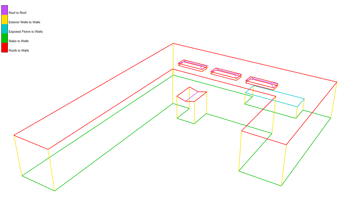
Nevertheless, I was able to add some methods to the Honeybee Model object, which analyze and group the different types of edges across the envelope without double-counting them (as long as adjacencies are solved correctly across the model). I added them with this commit:
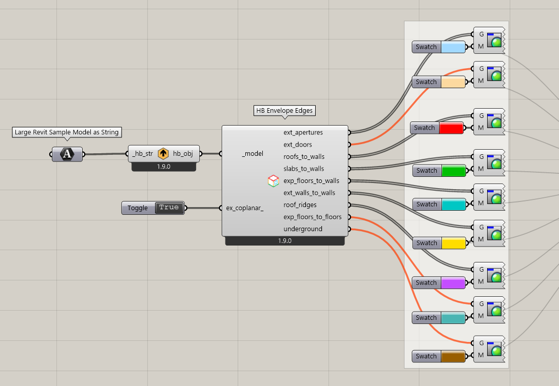
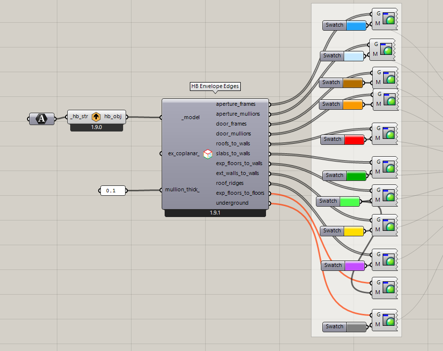
… and I added a new Grasshopper component that returns the edges for the different types of conditions with this PR:
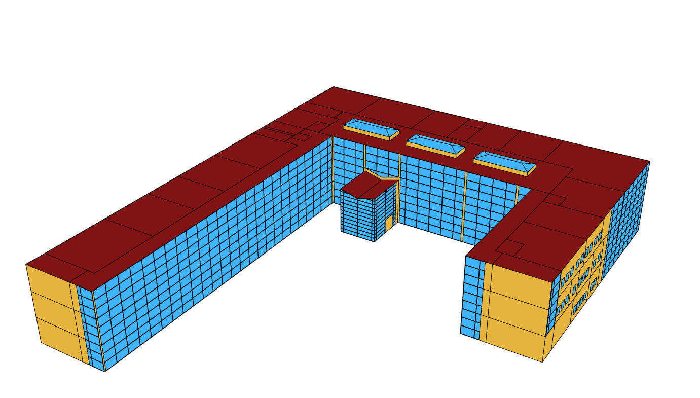
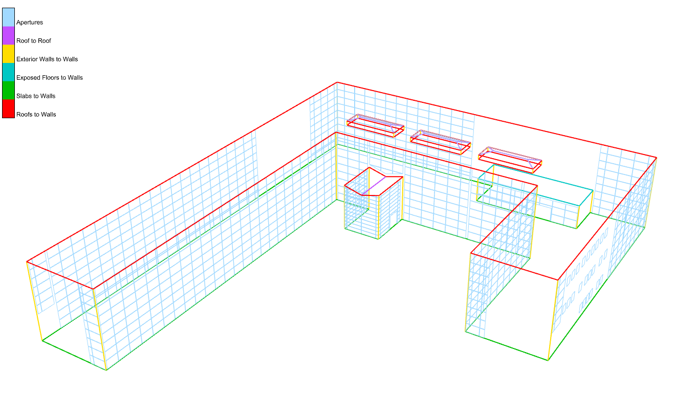
Here is a sample Grasshopper file showing how you can use it to visualize the different edge conditions across the large Revit sample model:
You have the option of getting the envelope edges between coplanar Faces thanks to the extra boolean option on the component (maybe this is useful for identifying balconies where two coplanar wall faces meet):
You can get the new component on your end, @edmay, by running the LB Versioner if you want to test it out. This should give you an automated way of getting many of the lines that are input to your honeybee-PH components.
Now that we have these new core methods, @mikkel will work on making use of them to generate a PDF report from the Model Editor with a record of all of these linear conditions (along with total lengths for the different edge types). Granted, I realize that a few of the thermal bridge cases are not things that our geometry schema supports because it is designed for energy and Radiance simulation. So we will be missing certain point conditions like structural penetrations or roof penetrations because our schema is not designed to analyze building structure or roof drainage. But many of the tougher-to-calculate bridges that lie along linear dimensions or areas are easily automatically calculated using our schema and our geometry library. So we can hopefully get you a PDF report feature in the near future that gets you most of the way there.
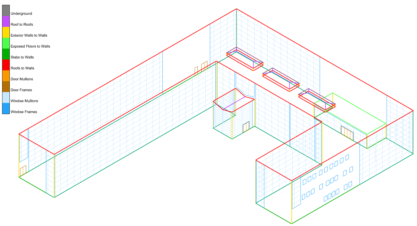
FYI, I could not help myself from thinking that the window perimeter lengths were just misleading/unhelpful because mullions tend to have very different psi values than frames and the length of mullions was kinda being double-counted between the two neighboring windows. So I added new routines to separate the mullion edges from the frame edges using a new mullion_thick_ input and I updated the component here:
I’d hope we can find a better alternative to THERM, I know that’s how PHIUS wants their TB’s modeled but that program is awful There has to be another option I’d hope these days.
Maybe:
I think that will get us 2 and 3D thermal modeling
A quick scan through Elmer does not offer me much confidence. What am I missing? I like Therm mostly because of the links to LBNL’s other clunker Window because of the latter’s connection to the brilliant underlying glazing materials database and ability to transition us into the BSDF future…
Elmer could provide 2D and 3D thermal modeling as well as fluid dynamics which could possibly offer a solution to a new version of butterfly, that seems like a decent option to me
The THERM discussion probably merits a separate discussion topic (and probably belongs on the LBT forum). But I’ll just say that I am planning to work on a new insect to connect to THERM in December. The 8.1 Beta version of THERM that LBNL released towards the end of September has two major improvements to it that remove big support headaches that I had with the Legacy Honeybee connection to THERM:
THMX is now the native file format of THERM 8.1. So the files that I could write from a new THERM plugin would be fully featured with full support for glazing systems (unlike the second-class citizen that THMX was in Legacy).
THERM 8.1 has a completely re-written meshing algorithm, which can do recursive quadtree subdivision up to 100 times (unlike that 8 times that we have had to contend with in previous THERM versions). This means that all of the intricate complexities that people have in their CAD-drawn construction details can now be accommodated by the THERM meshing algorithm. The previous max subdivision of 8 really only worked well for things drawn in the extremely limited THERM interface and not the world of real construction details.
Granted, some of my former headaches will still be there, like that fact that THERM is still closed source and only runs on Windows. The LBNL team has told me that they really want to release a C package for the THERM engine like the WINDOW calculation engine, which would address these issues. But the big problem is that the THERM engine is still written in FORTRAN and, while LBNL has started on a C version that could eventually be suitable for open sourcing, the funding for this is very low and not getting any better at the moment. So I don’t know how long it might be for these issues to be addressed.
Still, the recent 8.1 improvements have made the idea of a new THERM connection compelling enough that I am going to try this before resorting to something like cobbling together an Elmer Frankenstein with some other mesher, which I know comes with a lot of challenges.
Granted, I don’t want to stop anyone if they would want to try their hand at using the new THERM 8.1 or do their own Elmer experiments. But maybe we table the discussion here for now and, when I hopefully have a POC for a new THERM connection towards the end of December, we can continue the discussion on the LBT forum.
Let’s leave this thread for just discussing the thermal bridging quantity takeoff report here, which @mikkel is working on now and will post back here when it is ready for testing.